Custom Robotic Arm

Arm Iterations

A curated build log showing the arm's progression from CAD and manufacturable printed geometry into a wired, actuated physical prototype with a yaw base, shoulder transmission, trussed links, and gripper assembly.

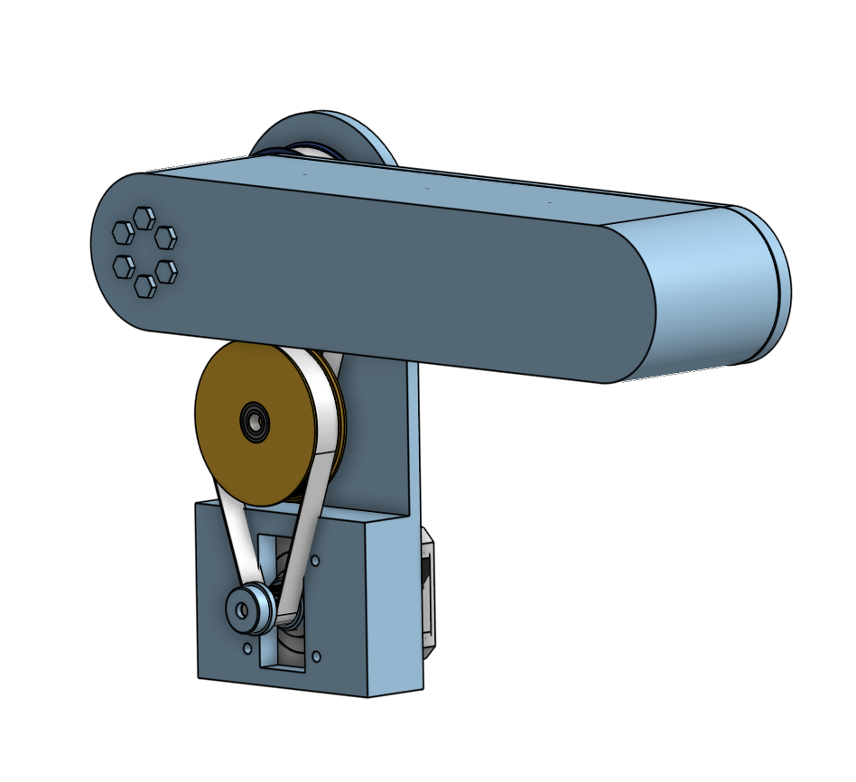
Early CAD concept of robotic arm shoulder belt reduction

Phase 01 / Early Shoulder Concept

Initial belt-reduction shoulder study

The first shoulder concept used a compact belt path around the shoulder axis to increase torque while keeping the motor inside the arm's mechanical envelope.

  • Established the basic motor-to-shoulder power-transfer direction.
  • Revealed that pulley diameter and belt wrap would be limited by packaging.
  • Created the design constraint that later led to a custom planetary reduction.
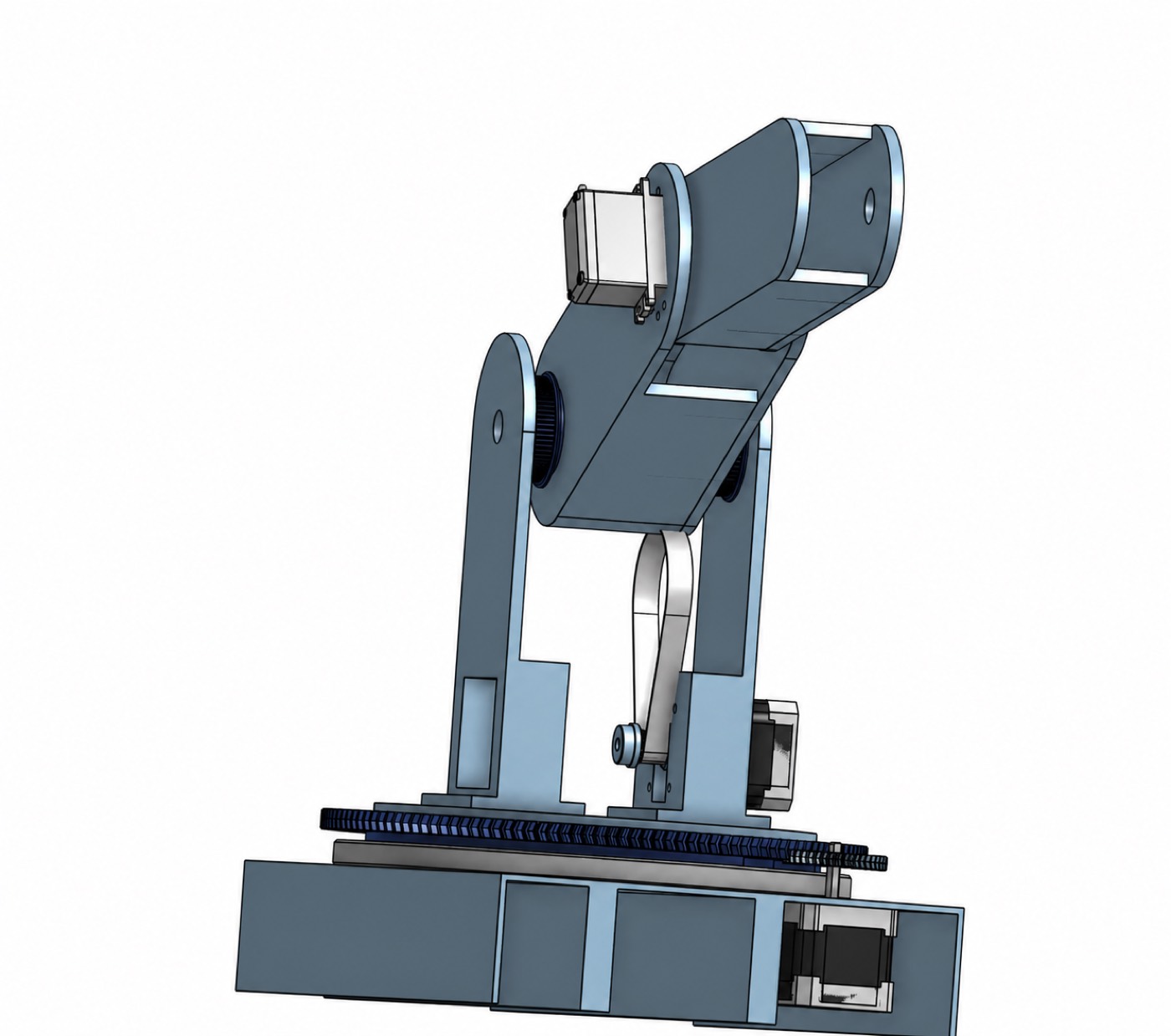
Cleaned early full CAD assembly of the robotic arm

Phase 02 / First Full Layout

Baseline arm and turntable architecture

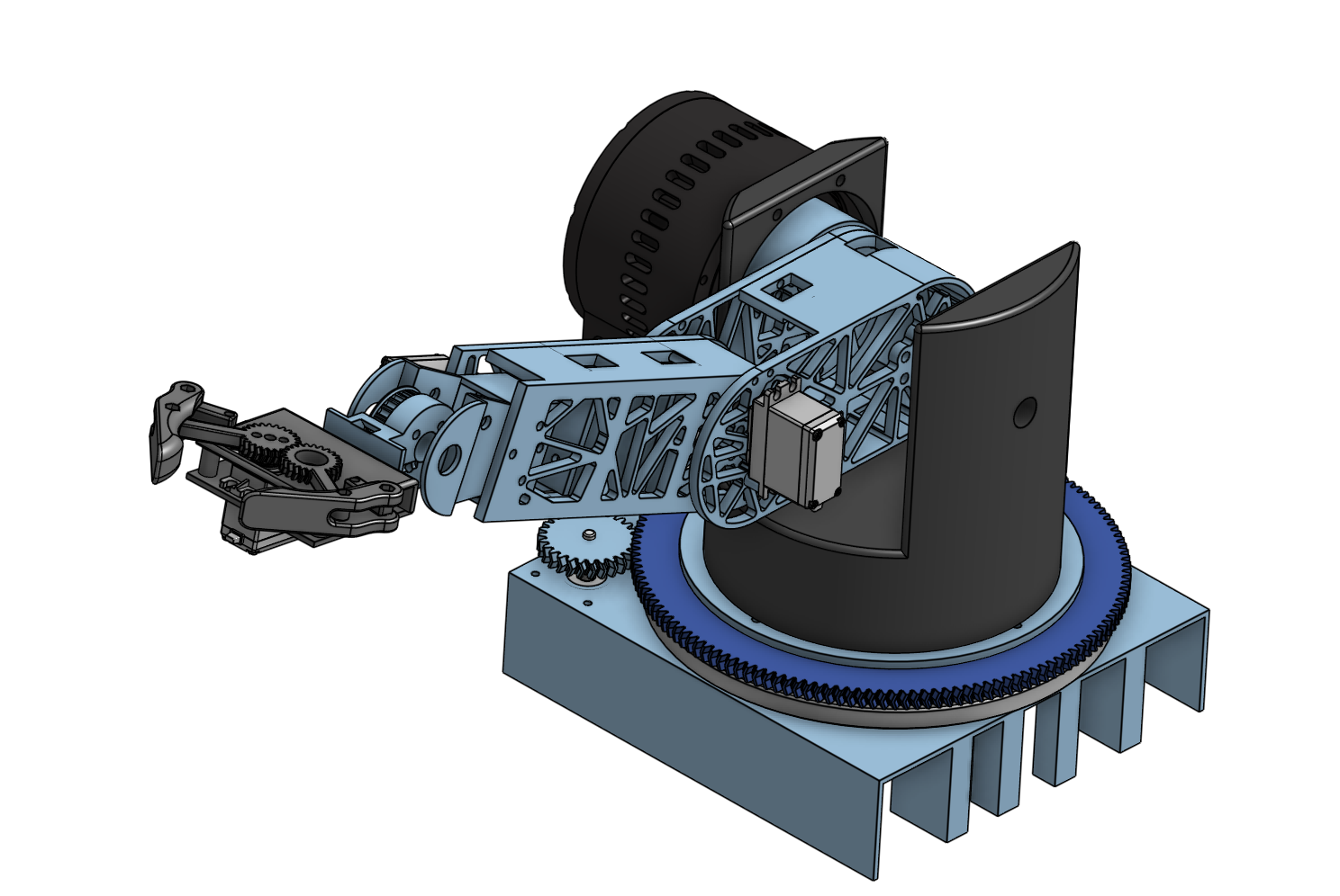
The first full layout established the yaw base, shoulder pitch axis, arm envelope, belt-driven base rotation, and rough actuator placement.

  • Defined the major rotational axes and overall reach of the arm.
  • Connected the base ring gear and upper arm geometry into one system.
  • Exposed where structure, actuation, and wiring would compete for space.
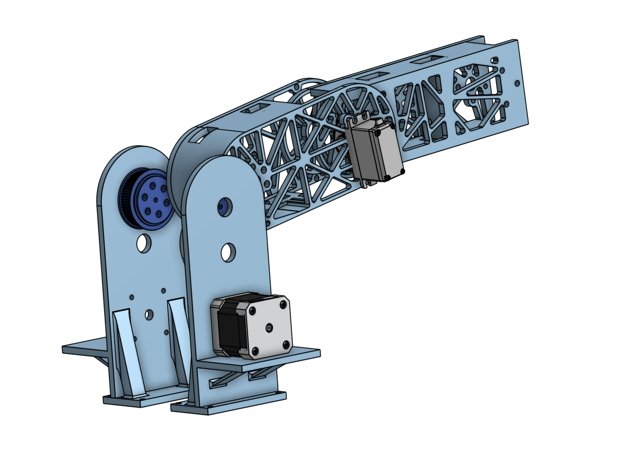
CAD model of trussed robotic arm shoulder link

Phase 03 / Link Structure

Trussed shoulder link and actuator mount

The arm moved away from solid members toward a trussed link, reducing mass while keeping bending stiffness and providing integrated actuator mounting points.

  • Used triangular ribbing to improve stiffness-to-weight ratio.
  • Positioned the motor mount close to the shoulder structure.
  • Refined the link around printability, fastener access, and joint clearance.
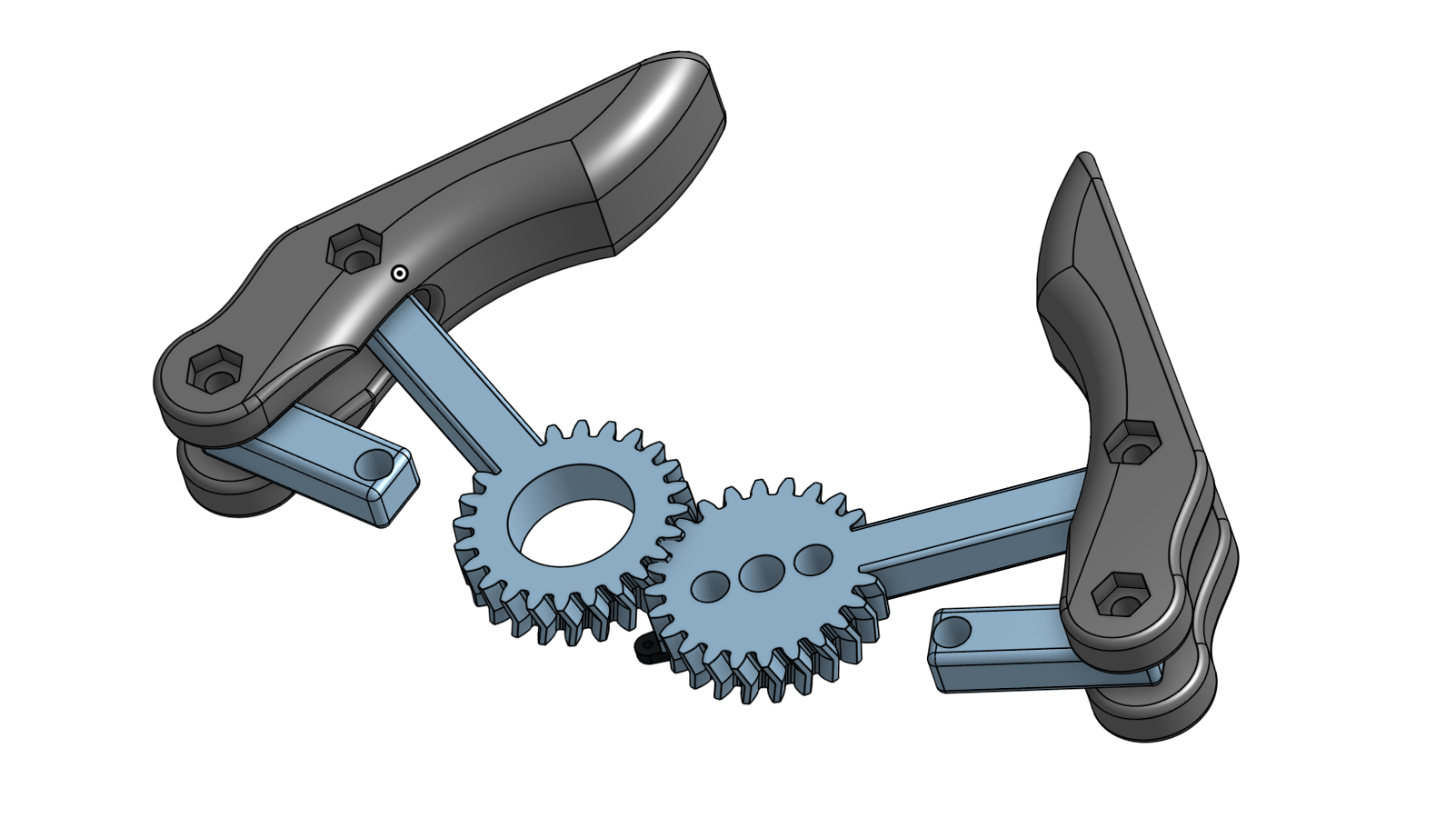
Geared gripper mechanism designed for the robotic arm

Phase 04 / End Effector

Geared gripper mechanism

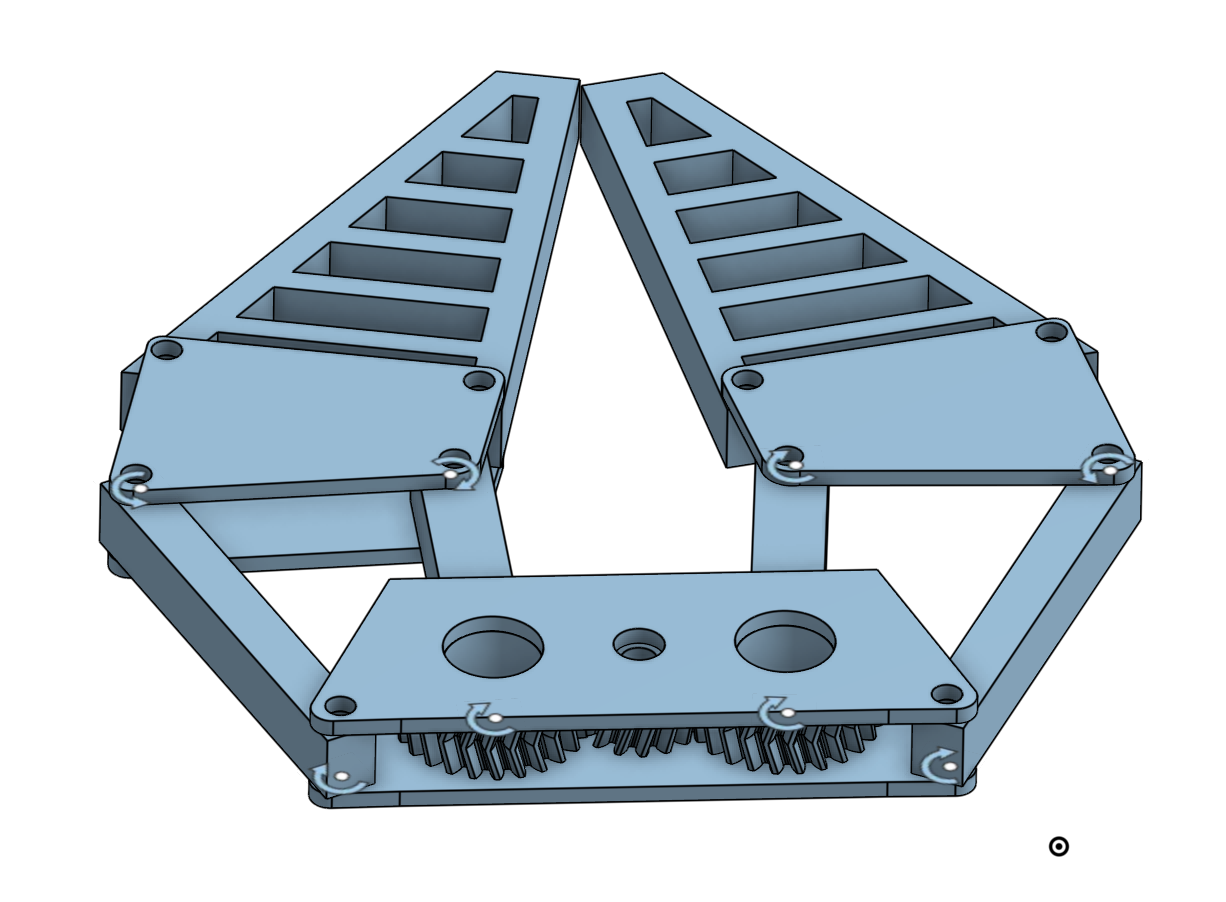
The end effector became a dedicated geared subassembly rather than a simple claw, improving symmetry, closure control, and future compatibility with autonomous manipulation.

  • Used meshed gears to coordinate opposing finger motion.
  • Added pivot geometry and linkage spacing for stable gripping.
  • Separated the gripper module from the arm body for easier iteration.
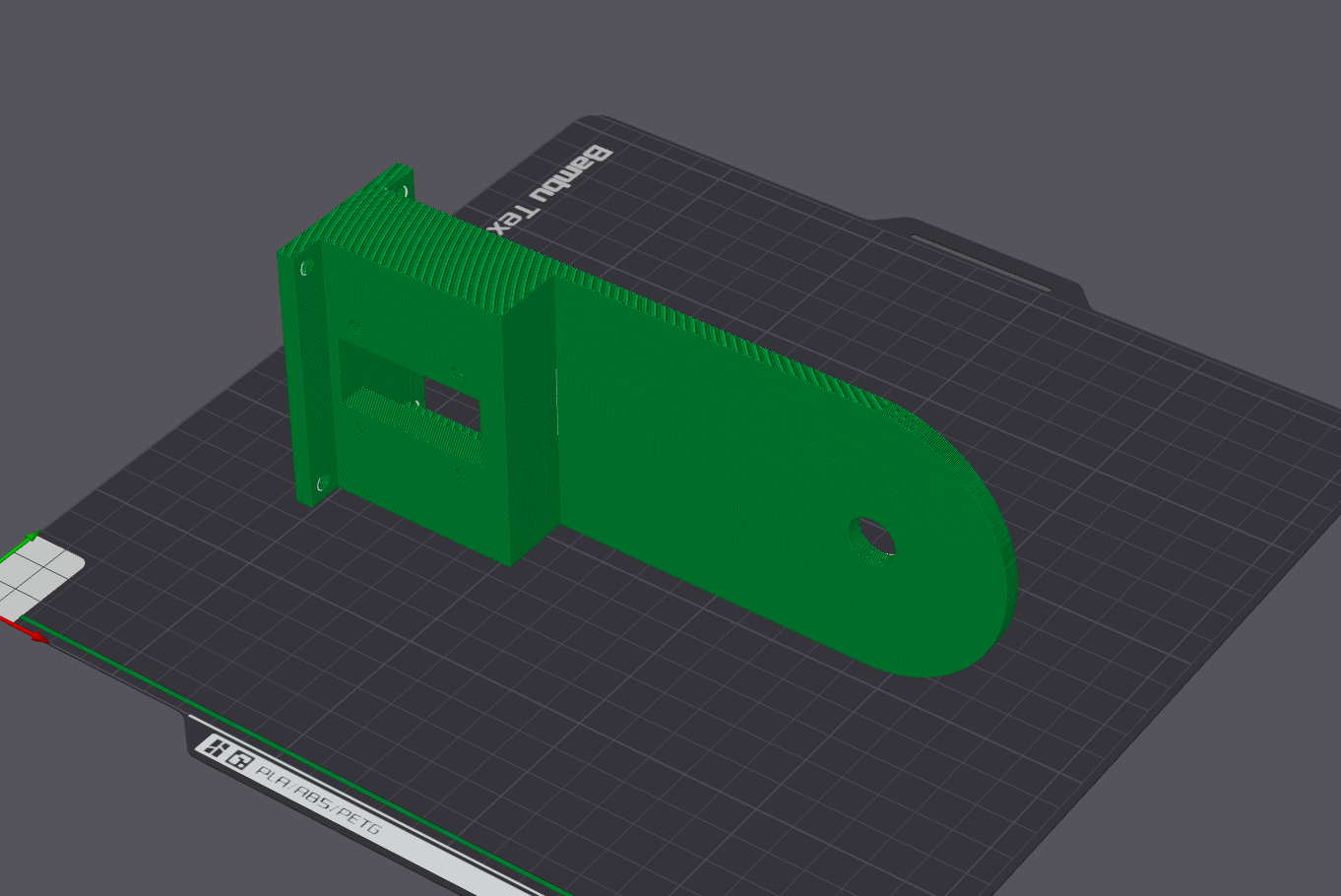
Sliced shoulder plate prepared for 3D printing

Phase 05 / Manufacturing Setup

Printed shoulder plate preparation

CAD moved into slicer preparation, where shoulder geometry had to be checked against print orientation, material settings, support needs, and hole tolerances before committing to physical parts.

  • Prepared a load-bearing shoulder side plate for additive manufacturing.
  • Checked printability of motor cutouts, mounting holes, and curved joint geometry.
  • Used slicing feedback to catch fit issues before fabrication.
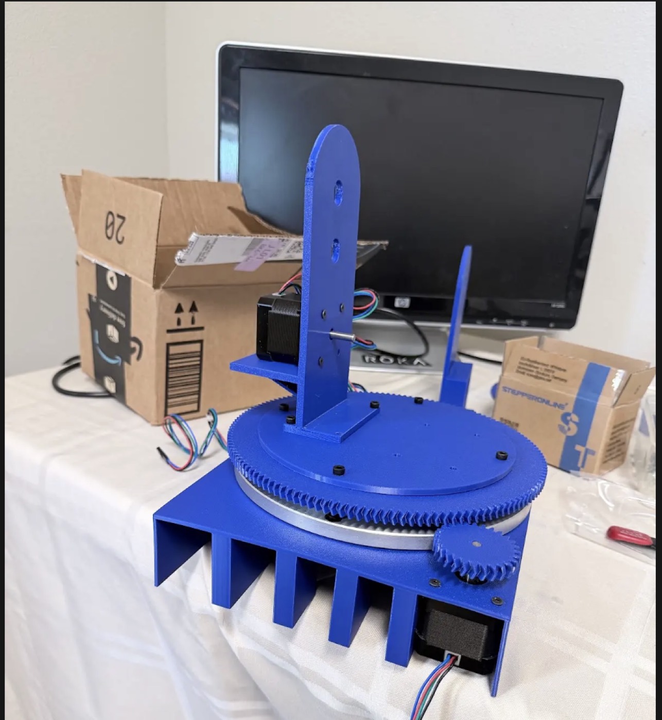
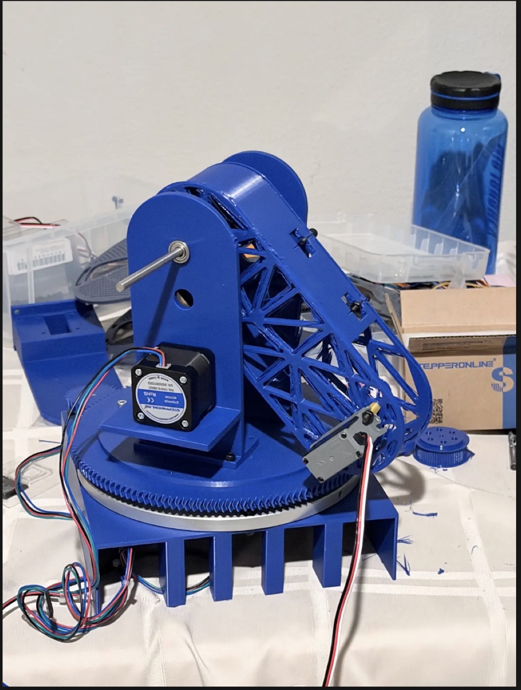
Printed robotic arm base with ring gear and vertical shoulder supports

Phase 06 / Base Fabrication

Printed yaw stage and ring gear

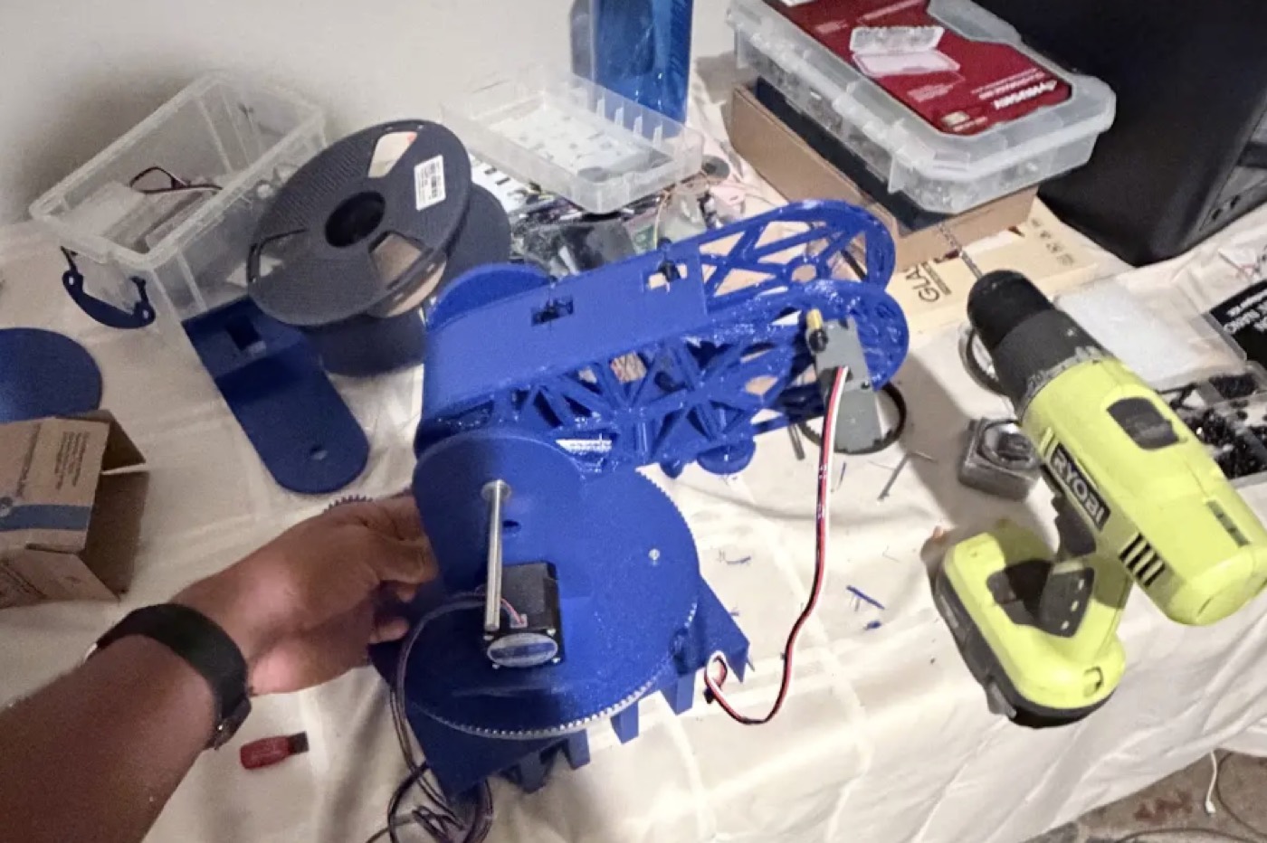
The first major physical subsystem translated the CAD turntable into a printed yaw platform with a large ring gear, motor mount, vertical shoulder plates, and a broad support footprint.

  • Validated bearing clearance and concentric gear alignment on the base.
  • Established the structural reference frame for the shoulder joint.
  • Kept the yaw actuator accessible for gear, belt, and wiring adjustments.
Printed trussed arm linkage mounted to the robotic arm base

Phase 07 / Linkage Fit-Up

Trussed arm mounted to the shoulder axis

The arm link was moved from CAD into a physical trussed member, making stiffness, shaft alignment, fastener access, and link clearance visible under real assembly constraints.

  • Used open truss geometry to reduce mass while resisting bending.
  • Checked shoulder-axis spacing against the printed side plates.
  • Confirmed that servo and linkage hardware could be accessed after assembly.
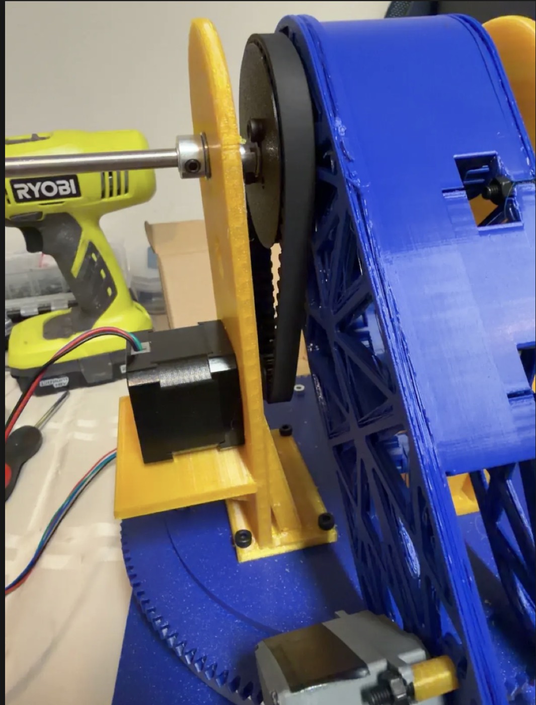
Close-up of physical belt-driven shoulder transmission

Phase 08 / Belt-Based Prototype

Physical shoulder pulley and belt fit-up

The printed prototype still reflected the original belt-drive direction, making the packaging problem visible in hardware: the shoulder needed more torque, but the available space limited pulley diameter and reduction ratio.

  • Tested shaft alignment, pulley spacing, and belt tracking in the printed shoulder.
  • Confirmed that packaging constraints limited the practical belt reduction.
  • Motivated the later custom planetary actuator as a compact torque solution.
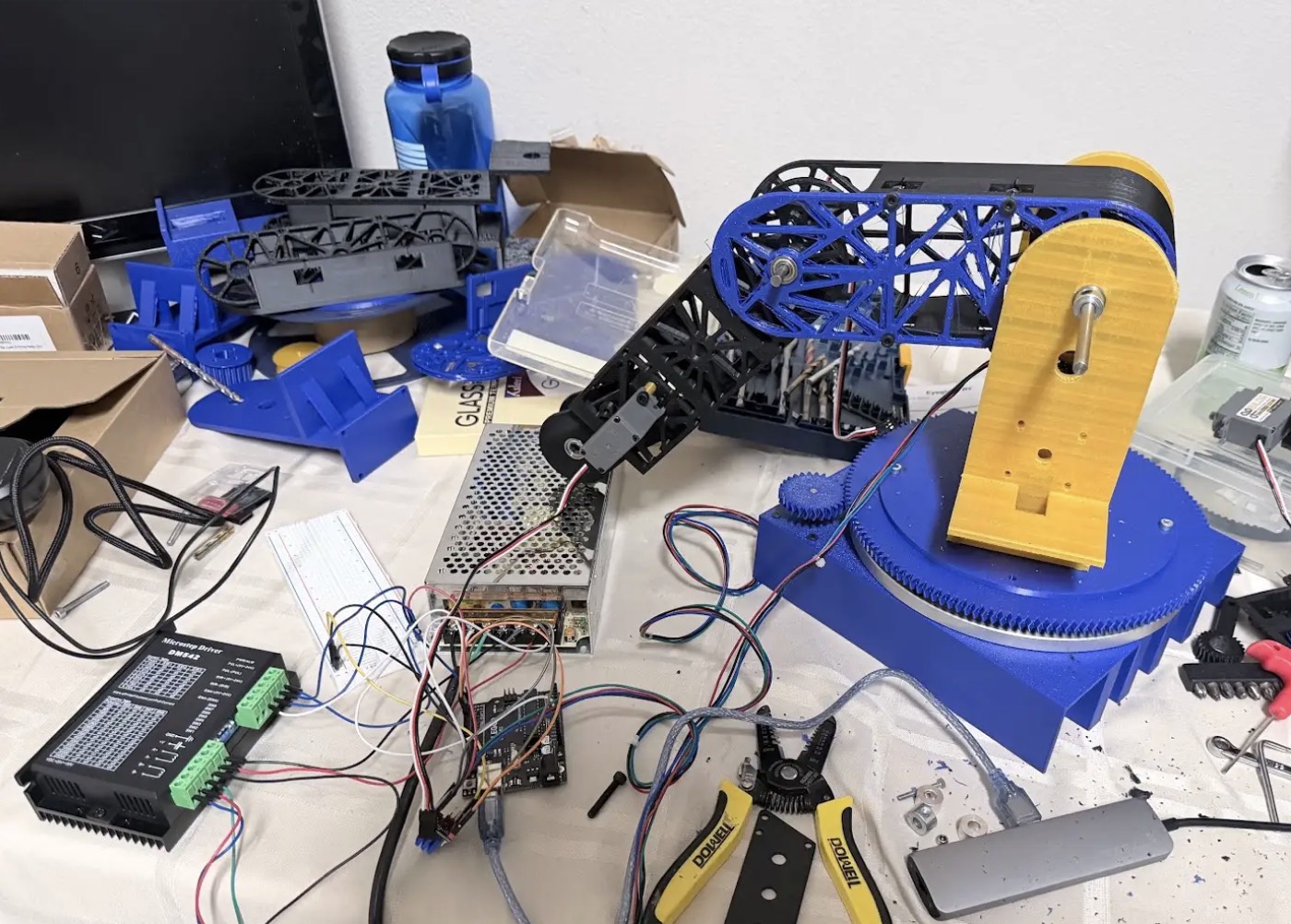
Integrated robotic arm prototype on a workbench with electronics and wiring

Phase 09 / Integrated Prototype

Multi-axis bench assembly

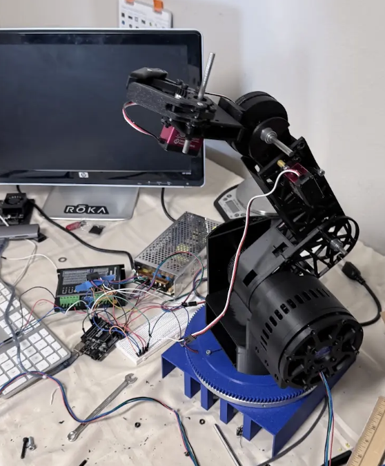
The arm reached a more complete hardware state with base rotation, shoulder actuation, elbow linkage geometry, wiring, and control hardware all present in one test setup.

  • Evaluated system-level packaging instead of isolated CAD parts.
  • Revealed cable-routing constraints around moving joints and rotating structures.
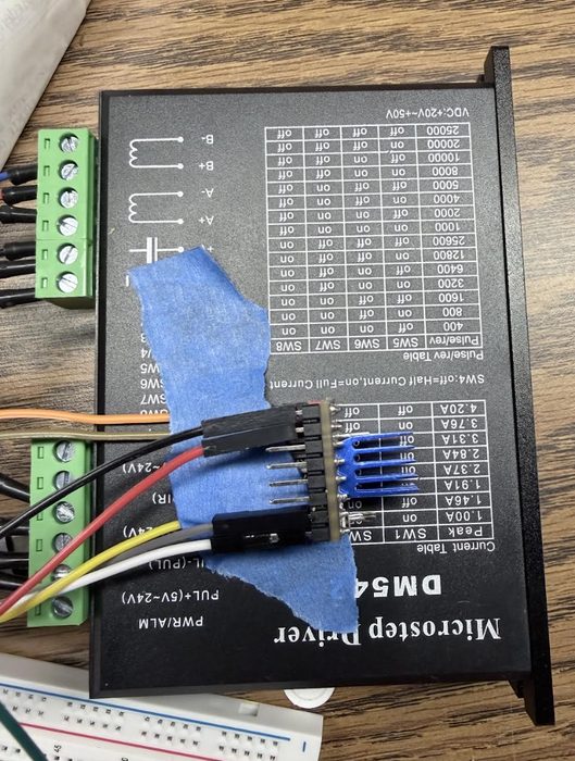
  • Connected mechanical design decisions to real actuator and driver behavior.
Section view of custom planetary shoulder drive Exploded CAD view of custom planetary shoulder drive

Phase 10 / Custom Actuator

Planetary shoulder drive for compact torque multiplication

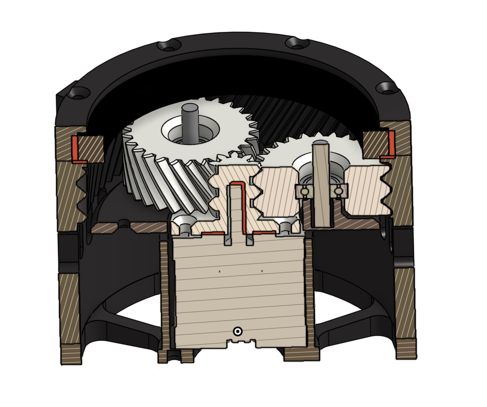
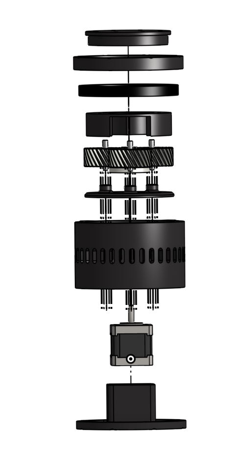
After the belt-driven prototype showed that packaging prevented a large enough pulley reduction, the shoulder was redesigned around a custom planetary actuator. The exploded and section views show the gear stack, retained shafts, housing, and bearing support used to increase torque inside the constrained shoulder volume.

  • Used internal gear reduction to increase shoulder torque without enlarging the belt system.
  • Packaged planet gears, bearing support, shafts, and retaining geometry inside one shoulder module.
  • Turned a packaging limitation into a more compact, purpose-built drivetrain.
Final CAD assembly of the robotic arm with planetary shoulder module

Phase 11 / Final CAD Direction

Integrated CAD with planetary shoulder module

The final CAD revision brought together the trussed links, geared gripper, yaw ring gear, base structure, and compact shoulder actuator into a more complete system-level design.

  • Placed the custom shoulder drivetrain in the final mechanical envelope.
  • Integrated the end effector and link geometry around the actuator layout.
  • Created a more realistic reference for fabrication and assembly decisions.

CAD Components

Component-Level Design Breakdown

These CAD views separate the key subassemblies behind the final arm: the first pulley idea, the trussed shoulder link, the custom planetary drive, the end effector, and the integrated final model.

Early CAD belt reduction concept for shoulder joint
Belt-Reduction Shoulder Study Early shoulder-drive packaging study that showed the torque reduction problem could not be solved cleanly with pulley size alone.
Cleaned baseline CAD assembly of robotic arm
Clean Baseline Assembly Early full-system CAD layout after removing loose reference parts, showing the initial shoulder, base, and arm envelope.
CAD trussed link and shoulder support module
Trussed Link Module Lightweight arm link with triangular ribbing, integrated mounting geometry, and shoulder-side load transfer.
CAD paired linkage and gear transfer concept
Paired Linkage Gear Concept Intermediate linkage study using paired members and gear coupling to keep motion aligned while distributing joint loads.
Exploded CAD view of custom planetary shoulder drive
Custom Planetary Drive Stack Exploded view of the compact shoulder gearbox designed to multiply torque inside the limited shoulder package.
Section CAD view of custom planetary shoulder gearbox
Planetary Gear Section Section view showing the internal gear mesh, retained shafts, bearing support, and housing geometry for the shoulder drive.
CAD geared gripper mechanism
Geared Gripper Coordinated end-effector mechanism using meshed gears for symmetric finger motion and modular future iteration.
Final CAD robotic arm assembly
Final CAD Assembly Full-system CAD view combining the yaw base, trussed links, gripper, and compact shoulder drivetrain.
Load path Improved transfer of bending and torsional loads through the shoulder, elbow, and trussed link structure.
Actuation More deliberate actuator placement for torque delivery, packaging, and future closed-loop control.
Serviceability Better access to fasteners, wiring, and modular subassemblies for iteration and repair.